
μ-MIM® Technical Newsletter Vol. 37: Our Metal 3D Printing Technology
Our metal 3D printer goes into full scale operation as we have introduced in our technical newsletter and webinars. The printing system has been operated with a spot diameter of 35 µm, and the printing system with a special 15 µm spot is now available.
Launch of the long-awaited 15μm spot diameter system
In order to shorten the prototyping period of μ-MIM components, we have used Incus GmbH’s LMM (Lithography-based Metal Manufacturing) 3D printer for preliminarily prototypes since last summer. The lack of the prototyping system in house had resulted in complicated administration of confidential information and long prototyping periods before. However, the introduction of the LMM 3D printer has enabled us to save time significantly. We have successfully completed launching the printing system with a spot diameter of 15 µm, which can fabricate components with dimensional tolerance and surface condition quality closer to that of components manufactured using μ-MIM technology. Although the pandemic regulations hindered the visit of an Incus GmbH engineer from Austria to Japan, we finally completed launching the printing in full scale operation in late April.
Metal 3D printers with the LMM method expose a specific wavelength light to a mixture of photosensitive resin and metal powder in order to form components precisely through polymerisation reaction, and the formed components transform into metal components after debinding and sintering processes. In the debinding and sintering process of LMM component, the same devices and technologies used in μ-MIM technology can be applied. Since photosensitive resin used in metal 3D printing is different composition from the binder used in MIM, the LMM formed components are required to have optimised process conditions in the debinding process while the sintering conditions are as sames as μ-MIM. In other words, we are able to offer you prototypes with short delivery times using the same metal powder and sintering technology used in μ-MIM. In addition, by introducing a spot diameter of 15µm, we are able to fabricate moulded components closer to that of μ-MIM.
On the other hand, metal 3D printing prototypes have different aspects from μ-MIM prototypes such as a low surface roughness, thin wall structure limitation (200 μm at the thinnest part, less than 100 μm for μ-MIM), anisotropy appearing in mechanical strength depending on stacking direction that is unavoidable in metal 3D printers. Therefore, we provide our customers explanations about these points for each component drawing prior to prototyping.
Example: spot diameter gap comparison
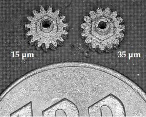
The left figure shows approx. 4 mm outside diameter gear samples which were debinded and sintered after forming with a spot diameter of 15 µm and 35 µm. This is an example of stainless steel 316L powder often used in μ-MIM components whose average powder size is 7 µm.
As the figure shows, they are the samples with a spot diameter of 15 µm on the left side and 35 µm on the right side, and you can see the shape differences of gear teeth and shaft. Although it is now possible to form finer shapes with higher precision, there is room for improvement. Thus, we are accumulating information and experience so that we can present samples formed under the appropriate conditions depending on shapes of components.
Column

Hello, I am Tomomi Takeno at the General Affairs Department. I have worked for the company for 11 months and now that I have a good grasp of my job, I am learning about different numbers and sentences on daily basis with the goal of doing my job efficiently. I am conscious of communicating appropriately and accurately in my work, not only to avoid inconveniencing customers, but also because I have many opportunities to interact with many people within the company.
Conclusion
Cracking, slumping or blistering is commonly observed due to the binder swelling and/or residual stress difference between the surface and interior. It is possible to avoid these problems by selecting appropriate organic solvents and temperature control.
The catalytic deboning uses sublimation of binder, thus it is possible to decompose the binder in relatively short processing time with minimizing the deformation. However, with a strong acidic atmosphere, theapplicable metal material option is limited.
In the sintering process, the necking, which is bridging the metal powders by thermal diffusion, starts at the sintering temperature. Once the necking starts, the shrinking is observed and increases the density, thus before starting the necking reaction, all the organic components should be decomposed and gas between the powders should be removed. In the sintering process, the unwanted chemical reaction, such as oxidation or carbonization, leads to mechanical property loss, therefore a precise atmosphere control with low heating rate at the beginning of the process is required. Also, when it reaches the sintering temperature, some add it vegetal can be evaporated.